Below are the questions asked during the live event, along with their respective answers.
Q: Can I shift antenna position either horizontally or vertically after calibration for testing? If no, why?
A: Once you’ve calibrated the field, you must perform the testing with the antenna in the same position for each and every test. If you don’t, then you’re violating the calibration that you’ve just performed. The antenna must be in the same physical location, including the same height you calibrated at.
Q: Why there is a difference in window method for 80 to 1Ghz (16 points)and 1 to 6GHz (4 points)?
A: This is because at the frequency increases, the field generated and antennas used become directional. Therefore the approach below 1 GHz and above 1 GHz are different.
Q: You mentioned voltmeter and allowed tolerance for immunity. Is the voltmeter set for a sensitive range or is each range required for test?
A: I don’t recall mentioning a voltmeter. However, for field probes, there should be a stated tolerance from the manufacturer. That tolerance should be stated within your calibration report for IEC 61000-4-3.
Q: How is a constant power field calibration done and what is its purpose?
A: The constant power calibration is covered in the presentation. First, step through the frequencies at the first position, achieving the field and recording the forward power required to generate it. Then, as you move through the other 15 points, replay the forward power and record the resultant field strength for each point.
Q: I don’t mean to be contradictory, but I thought it was 20% higher, not 80% higher.
A: 80% is given in the standard. See the figure below.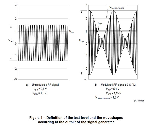
Q: Are floor absorbers mandatory as per standard?
A: Floor absorbers are not mandatory, but help greatly when attempting to perform UFA.
Q: Any height limitation for Floor absorbers as per standard?
A: There is no height limitation, but the absorbers should be short enough such that they are not inline with the antenna and the UFA location.
Q: Is the stub field validation affected by the EUT loading of the field?
A: Potentially, yes, especially with large metallic EUTs. So, perform the field verification prior to installing the EUT within the chamber.
Q: What is the influence of probe support (mast) material to the field uniformity?
A: The probe support should be of non-metallic material, as metallic material will influence the probe’s measurement.
Q: If you want to use multiple field probes, how do you account for an inherent error that is seen between them, despite accounting for the differences in calibration data?
A: You would need to discuss with the manufacturer of the probe on the proper distance that the probe needs to be located away from each subsequent probe.
Q: What is the best position of field probe during calibration?
A: The location of the field probe is defined in the standard to be within the 16-point grid.
Q: If you recommend removing the table during calibration how would you evaluate its impact on uniformity during the tests?
A: You don’t. The table is not allowed within the chamber during the calibration. The standard does not account for influence but does give discussion to construct the table out of non-conductive material.
Q: Is there any important technical difference in edition 4 of 61000-4-3 that could impact the needed hardware to perform the test?
A: Yes. The newest version of the standard, which is currently within FDIS awaiting signoff, includes the ability to test with multiple tones and how to handle that testing approach. Also, the upper frequency limit has been removed, so higher frequency equipment may be needed within the laboratories.
Q: Could the uniform area be only 4 points?
A: Yes, if you’re calibrating a UFA that is only 50 cm by 50 cm.
Q: Is there any benefit of using constant power instead of FS calibration?
A: The one benefit of using constant power is that you can use multiple field probes.
Q: Is it in presence of Modulation?
A: Calibration is performed CW (continuous wave).
Q: How do you choose between 2 Calibration methods (field or power)?
A: Up to the user; if one method fails, you can try the other method to see if results are better.
Q: %2B/-1dB is it not the limit of accuracy of spectrum analyzer?
A: I’m not sure I understand the question. The accuracy of your pretest measurement is dependant on the accuracy of your measurement device.
Q: What kind of pickup device can be used?
A: A small stub radiator or antenna should suffice.
Q: Could you confirm that 2dB compression is fine for amplifiers until complying to harmonic spec?
A: For the linearity/compression check, a 2 dB compression point is used.
Q: Are multiple antenna positions allowed for the higher frequencies where the antenna beamwidth limits coverage?
A: Yes, and the standard allows for windows to be utilized above 1 GHz.
Q: Is it allowed to change the height of the antenna from 1.55m to other values?
A: You can, as long as you meet the UFA requirements.
Q: Do you have any recommendation for what the first grid point should be?
A: I typically use the lower row as the starting point to ensure you can meet the field strength requirement, as this is the most difficult location.
Q: Why is the UFA limited to 0.5m x 0.5m?
A: This is a windowing method approach above 1 GHz. However, a 16 point grid is still preferred.
Q: Does an automotive radiated immunity test ISO 11452-2 also need to perform 16 point calibration?
A: No, that is typically a single point calibration.
Q: If an anechoic chamber is set up per MIL-STD or DO-160 testing, will the chamber meet the requirements for an anechoic chamber for 61000-4-3? Specifically Anechoic foam placement on the walls in relation to height from floor and table.
A: You will probably need to add floor absorber and reconfigure your tables, but I have done this when necessary.
Q: Comment on the requirement to perform evaluations on an additional row below the 16pt uniform plane. Is this going away in future editions of IEC 61000-4-3?
A: It is not going away, and is used to know what the field strength below the lowest calibrated row is. It is not part of the calibration math but is used for recording data purposes only.
Q: Can the field obtained with one probe be validated with another field probe? For example, the costumer probe? How can these two measurements compare?
A: This would require having the calibration factors of both probes. There will be inherent differences in the measurements, which is why both probes should be calibrated by an ISO 17025 accredited laboratory.