2017 Technical Webinar
Narrowband/Broadband – Not Just An Arcane Discrimination, but the Key to System-Level EMC Demonstration
Overview:
Laboratory demonstrations show why modern EMC testing uses the spectrum analyzer noise floor measurement as opposed to the older method of sampling radio channels and listening for noise. The attendee will witness a demonstration of the effects of narrow and broadband noise on both the ability of a victim radio to properly receive a signal, and also the ability of a test engineer to properly discern if there is interference.
Who Should Attend?:
EMC engineers working on planes, trains, automobiles, ships and spaceships.
Ken Javor
Ken Javor has worked in the EMC industry for thirty years. He is a consultant to government and industry, runs a pre-compliance EMI test facility, and curates the Museum of EMC Antiquities, a collection of radios and instruments that were important in the development of the discipline, as well as a library of important documentation. Mr. Javor is an industry representative to the Tri-Service Working Groups that write MIL-STD-464 and MIL-STD-461. He has published numerous papers and is the author of a handbook on EMI requirements and test methods. Mr. Javor can be contacted at ken. javor@emccompliance.com.
Q&A
The following questions were asked during the live presentation. Click each question to view its answer.
What is wrong with using a larger bandwidth for broadband signals? After all, they used to normalize to a 1 MHz bandwidth, right?
Here’s a real world example that illustrates all the issues.
A few decades ago, a professor at an aeronautical engineering department came up with a novel idea for deicing wings on small single engine aircraft, where the engine doesn’t produce enough heat to melt accumulating ice. He attached (riveted) spiral shaped pieces of metal to the inside of the wings’ leading edges at intervals down the length of the wing and these spirals acted as inductors in a circuit where the electronics charged a large cap to a high potential and then dumped that into the spiral inductors. This caused them to jerk, generating a shock acting and sounding like a hammer striking the inside of the wing, with the purpose of shaking loose any ice on the wing exterior.
By its nature this mechanism is impulsive, not only physically but electrically, meaning it produces a broadband signature in the frequency domain. We were prepared for that during EMI testing, but what was interesting was that the active rod antenna normally used below 30 MHz saturated during the transient event and had to be replaced with an older passive tunable rod antenna in order to correctly measure the peak field intensity.
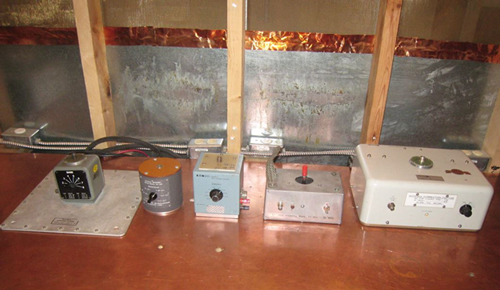
Three left-most rod antenna bases are passive tunables, two to the right are active wideband.
The reason for that was that the active rod antenna amplifier was seeing the entire transient spectrum over a 30 MHz plus range, and that was sufficient to cause saturation. So for the active rod antenna, it was entirely suitable to measure the dBuV/m/MHz in a 1 MHz bandwidth, correct up to 30 MHz and then compute the total signal and compare to the manufacturer’s specified maximum input.
But after ascertaining the not-too-surprising fact that the transient exceeded the radiated emission broadband limit for such aircraft, we decided to check the effect on a radio operating below 30 MHz. We used an AM broadcast band radio tuned to 1410 KQAM and closed the shield room door until the signal just started getting a little noisy, meaning we were approaching the radio’s internal noise floor. Operating the deicing equipment elicited no observable signal degradation in this condition.
This is due to the radio’s roughly 6 kHz bandwidth, which is way too small to capture a significant signal from the transient event. This qualitative statement can be quantified. The active rod antenna used was the one all the way to the right, the Model 95010-1, variously manufactured by Stoddart and later Singer and Eaton/Ailtech. The saturation level per the manufacturer’s data sheet is 107 dBuV, or 73 dBuV/m/MHz over a 50 MHz bandwidth, which in a 6 kHz bandwidth is just 29 dBuV, much less than the signal level we were actually receiving, even with the broadcast signal attenuated by the shield room.
The radio was exhibiting pulse desensitization: the effect of capturing only a small part of the spectrum of a wideband event. This illustrates that while the active antenna had to be evaluated using a wide bandwidth characteristic of its performance, using a wide bandwidth vastly overestimates the signal captured by a small bandwidth device.
While we just extrapolated analytically from a very large bandwidth to a small one, in the general case most signals aren’t this wideband, and linear extrapolations over orders-of-magnitude differences are not accurate. The best practice is to always use a measurement bandwidth characteristic of the victim protected by the levying of the radiated emission limit. In a case such as this one where there were two components to the measurement system that are sensitive in one case very wideband and in the other case very narrowband, it might make sense to make two separate measurements using different bandwidths, although these days it is heresy to say so…
That deicing system must not have worked too well. I haven't seen one in use in anything I've flown.
Can’t say, it was some aeronautical dept. professor’s project at Wichita State University. Always wondered about the long term structural effect on the wing.
It is called pulse desens when your filter time is longer than your pulse.
Yes, but that implies a bad measurement vs. when a short pulse interferes with a low BW radio. It isn’t as much of a problem as a long pulse.